RaceCapture by Autosport Labs

RaceCapture by Autosport Labs
RaceCapture is the brand name of a vehicle data acquisition and telemetry hardware platform offered by AutoSport Labs. The brand offers a range of hardware for motorsports applications.
RaceCapture Track MK2/MK3
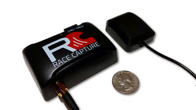
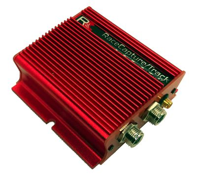
The Track MK2 and Track MK3 are compact entry level hardware platforms that are perfect for the motorsport enthusiast looking to improve their skill and shave time. Both models integrate easily into the CAN Bus and OBD-II Ports of modern production vehicles making access to vehicle data a near Plug and Play Installation.
Auto Sport Labs also provides an App available for both iOS and Android mobile devices. The RaceCapture App is strongly geared towards circuit type driving and works great for monitoring vehicle performance and lap times during track day events.
As for AutoCross, Stage or Point to Point oriented competitions we have found that SoloStorm by Petrel Data Systems to be a better option. However, SoloStorm availability is limited to Android mobile devices.
G29/J29 PT-CAN Bus Install
On BMW vehicles, the PT-CAN Bus is the network that is used to transmit power train data to other subsystems throughout the vehicle. By tapping into the PT-CAN Bus, the RaceCapture device passively collects data from the high-speed communication between modules on the CAN Bus. It utilizes configured message maps to log data every time the target message appears on the bus.
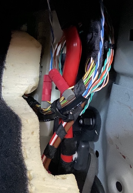
The easiest location to tap into the PT-CAN Bus on the G29/J29 platform is in the passenger outer footwell. Remove the plastic kick panel trim to gain access to the wiring harness. The PT-CAN is a twisted pair of wires with color codes Yellow/White (CAN HI) and Yellow/Black (CAN LO).
Use a pair of Posi-Taps to tap the wires as shown.
G29/J29 D-CAN Bus Install
On BMW Vehicles, the D-CAN Bus is the network connection that is used to send and receive vehicle diagnostic messages. This is the network that will be used to request OBD Service 0x01 and OBD Service 0x22 PID Data. Integration into the D-CAN Bus can be done in one of two ways: Use the supplied OBD-II Cable or tap directly into the D-CAN Bus.
The easiest and most basic method to connect to the D-CAN Bus is via the OBD-II Port connector and supplied OBD-II Cable. Be mindful that the OBD-II port is always powered and that leaving the device connected while not in use may result in a discharged battery.
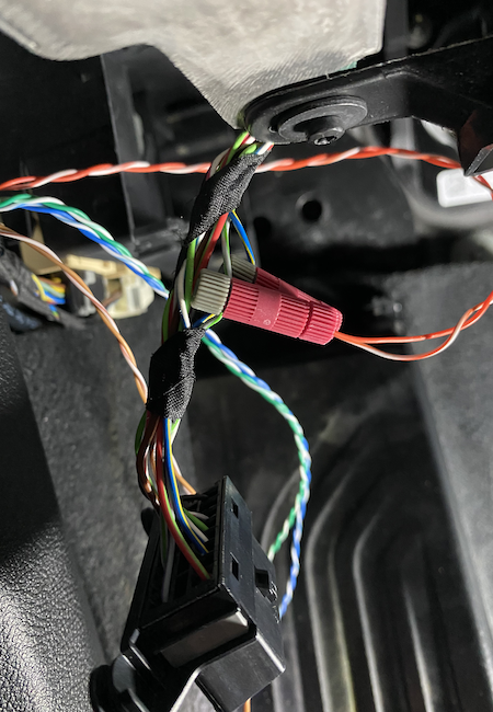
Another method to connect to the D-CAN Bus is via direct tap. In the driver footwell, release the OBD-II connector from the connector retainer to gain workable access to the wiring harness. The D-CAN is a twisted pair of wires with color codes White/Green (CAN HI) and Blue/Yellow (CAN LO).
Use a pair of Posi-Taps to tap the wires as shown.
Track MK2 CAN Bus Breakout
The RaceCapture Track MK2 is very compact and very light weight. Unfortunately, the CAN Bus connections and power connections are all contained within a single Female RJ-45 connector. For a user that is only interested in OBD-II PID data, simply connect the OBD-II cable and you’re all set. For others who desire to utilize CAN Bus 1 and CAN Bus 2 to collect a wider range of data, this presents a minor problem.
The following is an example of how to make a simple but effective RJ-45 based breakout assembly that will allow the end user to easily configure the MK2 wiring connections across two (2) separate RJ-45 ports. The assembly is constructed from two female RJ-45 modular wall connectors, Loctite plastic bonding glue, and a standard network patch cord.
 Loctite Plastic Bonding Glue
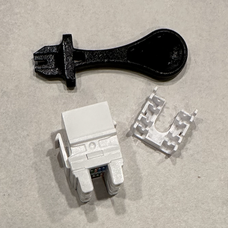 Modular Ethernet Jack
Apply primer and glue to the RJ-45 connectors and glue them together as shown below:
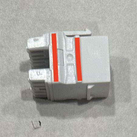 Apply primer and glue along the red lines.
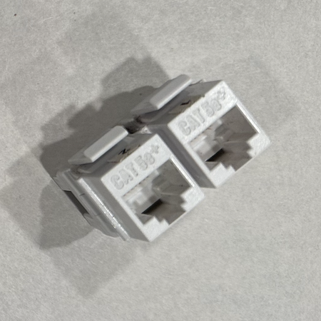 Connectors glued together (front).
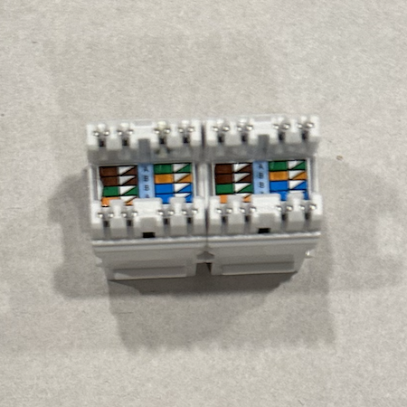 Connectors glued together (rear).
Now to connect the network patch cord. Mock up the patch courd routing from the Track MK2 to the desired location for the breakout assembly. In this example, the Track MK2 and the breakout assembly are located directly adjacent to each other.
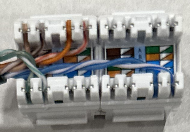
Cut a network cable approximately two (2) inches longer than needed and remove the last two (2) inches of outer insulation. Use the included “punch down” tool to insert the network cable wires into the connection slots and trim the excess wire. See "punch down" examples detailed below.
This assembly allows the user to easily configure the pin/wire arrangement into whatever configuration is needed.
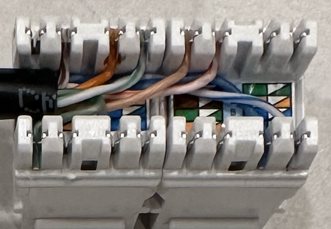
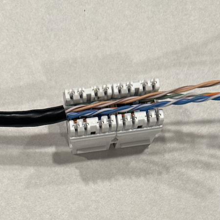 Stripped wire ready for punch down.
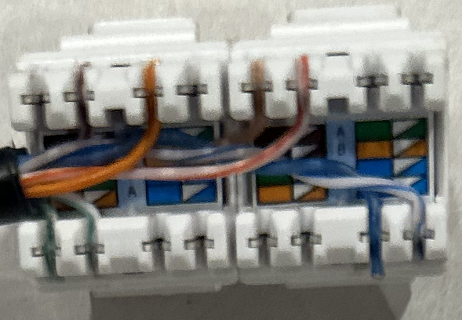
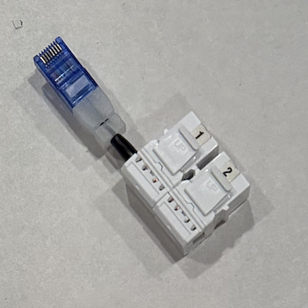 Fully assembled breakout connector.
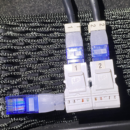 Completed connector ready for use.
Example #1
Port 1 contains Power and CAN1 as is configured to be used with the standard OBD-II cable. Port 2 contains CAN2.
 | |||
| PORT | PIN | COLOR | SERVICE |
| Port 1 | Pin 1 | Orange/White | GROUND |
| Port 1 | Pin 2 | Orange | CAN 1 (HI) |
| Port 1 | Pin 3 | Green/White | CAN 1 (LO) |
| Port 1 | Pin 8 | Brown | 12 VDC |
| Port 2 | Pin 4 | Blue | CAN 2 (HI) |
| Port 2 | Pin 5 | Blue/White | CAN 2 (LO) |
Example #2
Port 1 contains CAN1 and is configured to be used with the standard OBD-II cable. Port 2 contains Power and CAN2.
 | |||
| PORT | PIN | COLOR | SERVICE |
| Port 1 | Pin 2 | Orange | CAN 1 (HI) |
| Port 1 | Pin 3 | Green/White | CAN 1 (LO) |
| Port 2 | Pin 4 | Blue | CAN 2 (HI) |
| Port 2 | Pin 5 | Blue/White | CAN 2 (LO) |
| Port 2 | Pin 7 | Brown/White | GROUND |
| Port 2 | Pin 8 | Brown | 12 VDC |
Example #3
Port 1 contains CAN1 and is configured to be connected by direct tap. Port 2 contains Power and CAN2.
 | |||
| PORT | PIN | COLOR | SERVICE |
| Port 1 | Pin 1 | Orange/White | CAN 1 (LO) |
| Port 1 | Pin 2 | Orange | CAN 1 (HI) |
| Port 2 | Pin 4 | Blue | CAN 2 (HI) |
| Port 2 | Pin 5 | Blue/White | CAN 2 (LO) |
| Port 2 | Pin 7 | Brown/White | GROUND |
| Port 2 | Pin 8 | Brown | 12 VDC |

- © The SECRET Ingredient!. All rights reserved.
- 4/27/2024